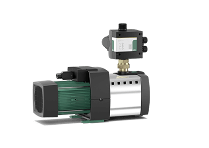
Wilo-Isar MODH1-1

Explanation of the name

Example: Wilo-ISAR MODH1-1CH1-L-202 / EC
Wilo Brand
ISAR Multi-stage pressure booster
MOD Commercial Series
H Booster set with horizontal pumps
1 Product Level (1 = Market Entry, 3 = Standard, 5 = Premium)
1 Number of pumps
CH1-L Pump Series
2 Nominal volumetric flow [m3 / h] single pump
02 Number of stages of a single pump
EC Easy Controller

Overview

High operational reliability thanks to installation with one, two or three horizontal CH1-L multistage pumps and stainless steel hydraulic part
Easy installation and maintenance thanks to special, flexibly adjustable connections to the storage pipe system
Easy commissioning and operation with Easy Controller
ACS and KTW approval for drinking water applications with stainless steel construction parts in contact with the pumped liquid

Type

Pressure boosting station with 1, 2 or 3 normally aspirated stainless steel high-pressure multistage centrifugal pumps connected in parallel

Application

  • Fully automatic water supply and pressure boosting with mains water or from a tank for private, commercial, industrial and municipal applications (e.g. residential, office and administration buildings, hotels, hospitals, industrial facilities, water supply companies).
  • Pumping drinking water, process water, cooling water or water for other technical purposes that does not chemically or mechanically attack the materials used and does not contain abrasive or long-fibre constituents

Equipment/function

  • 1 to 2 or 3 CH1-L pumps per unit
  • Corrosion resistant construction parts in contact with the pumped liquid
  • Galvanized base frame with height adjustable anti-vibration mounts for structure-borne sound insulation
  • Shut-off valve on suction and pressure side of each pump
  • Pressure check valve on the pressure side
  • Pressure gauge on the discharge side
  • Pressure gauge option on suction side
  • Pressure gauge on discharge side
  • Optional - Dry run protection
  • EC controller with IP54 plastic housing, consisting of an internal power supply unit, microprocessor, analog and digital input and output modules

Scope of delivery

  • Pressure boosting system factory assembled, tested for faultless function and tightness, ready for connection
  • Packaging
  • Installation and operating instructions

Model overview

Products


Product designation Network connection Maximum working pressure PN Number of pumps Number of standby pumps Unit capacity without standby pump Q Gross weight approx. m Article number
ISAR MODH1-1CH1-L-202/EC 3~400 V, 50 Hz 10 bar 1 0 - 58.0 kg 2551895
ISAR MODH1-1CH1-L-203/EC 3~400 V, 50 Hz 10 bar 1 0 - 59.0 kg 2551896
ISAR MODH1-1CH1-L-204/EC 3~400 V, 50 Hz 10 bar 1 0 - 59.0 kg 2551897
ISAR MODH1-1CH1-L-205/EC 3~400 V, 50 Hz 10 bar 1 0 - 61.0 kg 2551898
ISAR MODH1-1CH1-L-206/EC 3~400 V, 50 Hz 10 bar 1 0 - 61.0 kg 2551899
ISAR MODH1-1CH1-L-207/EC 3~400 V, 50 Hz 10 bar 1 0 - 62.0 kg 2551900
ISAR MODH1-1CH1-L-402/EC 3~400 V, 50 Hz 10 bar 1 0 - 58.0 kg 2551901
ISAR MODH1-1CH1-L-403/EC 3~400 V, 50 Hz 10 bar 1 0 - 59.0 kg 2551902
ISAR MODH1-1CH1-L-405/EC 3~400 V, 50 Hz 10 bar 1 0 - 59.0 kg 2551903
ISAR MODH1-1CH1-L-405/EC 3~400 V, 50 Hz 10 bar 1 0 - 61.0 kg 2551904
ISAR MODH1-1CH1-L-406/EC 3~400 V, 50 Hz 10 bar 1 0 - 63.0 kg 2551905
ISAR MODH1-1CH1-L-407/EC 3~400 V, 50 Hz 10 bar 1 0 - 63.0 kg 2551906
ISAR MODH1-1CH1-L-602/EC 3~400 V, 50 Hz 10 bar 1 0 - 59.0 kg 2551907
ISAR MODH1-1CH1-L-603/EC 3~400 V, 50 Hz 10 bar 1 0 - 63.0 kg 2551908
ISAR MODH1-1CH1-L-605/EC 3~400 V, 50 Hz 10 bar 1 0 - 63.0 kg 2551909
ISAR MODH1-1CH1-L-606/EC 3~400 V, 50 Hz 10 bar 1 0 - 67.0 kg 2551910
ISAR MODH1-1CH1-L-1002/EC 3~400 V, 50 Hz 10 bar 1 0 - 62.0 kg 2551911
ISAR MODH1-1CH1-L-1003/EC 3~400 V, 50 Hz 10 bar 1 0 - 66.0 kg 2551912
ISAR MODH1-1CH1-L-1004/EC 3~400 V, 50 Hz 10 bar 1 0 - 70.0 kg 2551913
ISAR MODH1-1CH1-L-1005/EC 3~400 V, 50 Hz 10 bar 1 0 - 71.0 kg 2551914

Those. information

Technical specifications

  • Electrical connection 3-phase 400 V ± 10 %, 50 Hz; 3~380/440 V ± 10 %, 60 Hz, depending on type also 1-phase 230 V, 50/60 Hz (other versions on request)
  • Max. medium temperature 50 °C (optionally 70 °C)
  • Max. ambient temperature 40 °C
  • Working pressure 10 bar
  • Inlet pressure 6 bar
  • Nominal diameter for connection on the discharge side R 2"/DN 100
  • Nominal diameter for connection on supply side R 2"/DN 100
  • Protection class IP 54
  • Fuse protection A, AC 3 on the supply side according to motor output and power supply company regulations
  • Permissible pumped liquids (other fluids on request). Approved liquids are water, which does not contain abrasive or long-fibre constituents and which does not attack the materials used chemically or mechanically.
  • Cooling water
  • Drinking water and process water

Materials

  • Single pump:
  • Impellers, section chambers and pump casing made of stainless steel 1.4301/1.4404
  • Stainless steel 1.4404 shaft
  • EPDM (EP851)/FKM (Viton) seal
  • Tungsten Carbide/Carbon Carbide mechanical seal
  • Bearings made of tungsten carbide
  • Pump mount in aluminum

Description/structure

  • Foundation frame: galvanised, with height-adjustable anti-vibration mounts for complete isolation of casing-borne sound, other versions on request
  • Piping system: complete piping system in stainless steel suitable for the connection of all types of piping used in plant engineering; the piping system should be sized for the total hydraulic capacity of the pressure boosting plant
  • Pumps: 1 to 2 or 3 pumps of series CH1-L 2, 4, 6, 10 in parallel connected; all components in these pumps that come in contact with the fluid to be pumped are made of stainless steel 1.4301/1.4404
  • Fittings: Every pump is equipped with shut-off valve or ring-shaped shut-off valves on the suction and pressure sides and, on the pressure side, with a non-return valve.
  • Diaphragm pressure vessel 8 l/PN 10 with butyl rubber diaphragm on the discharge side, completely safe in accordance with food safety regulations; equipped with a shut-off ball cock for testing and inspection as well as drains and flow fittings according to DIN 4807
  • Pressure sensor: 4 to 20 mA, arranged on the end pressure side for controlling the central EC
  • Pressure display: pressure gauge (ø 63 mm) on the discharge side; additional digital indication of the discharge pressure on the alphanumeric LCD display of the EC controller
  • Controller: The unit is equipped with an EC controller as standard

Download

Colors

DOP

Wilo CAD

The Wilo CAD online library contains DWG drawings of Wilo pumping equipment. In this library, the dimensions of the pumping equipment are given as a guideline. Please note that the contents of the Wilo CAD online library are subject to technical changes.


More in this category:

Need a consultation?

We will tell you in detail about our services, types of work and typical projects, calculate the cost and prepare an individual offer!