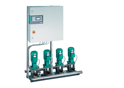
| Example: | Wilo-SiBoost Smart 1 MVISE 206 |
| SiBoost Smart | Compact booster system with integrated speed control |
| 1 | Number of pumps |
| MVISE | Pump Series |
| 2 | Nominal flow / [m ³ / h] single pump |
| 06 | Number of stages of a single pump |
Low-noise, ready-for-connection water-supply unit with vertically arranged normal-suction stainless steel high-pressure multistage centrifugal pump of MVISE series in glanded version with integrated water-cooled frequency converter.
1 MVISE series pump with glandless motor, speed-controlled by means of an integrated frequency converter, on a galvanised steel base frame for height-adjustable operation.
All parts in contact with the pumped liquid are corrosion resistant.
Baseframe: galvanized steel, with height-adjustable anti-vibration mounts, providing good structure-borne sound insulation, as well as integrated rigging points
Piping system: Complete piping system in stainless steel on the pressure side, suitable for connecting piping made of any material used in building equipment. The piping system is designed in accordance with the total hydraulic capacity of the pressure boosting unit.
Pumps: 1 MVISE 2, 4, 8 series pump is used. The water-cooled frequency converters on the pump motor provide infinitely variable speed control ranging from 20 Hz to a maximum of 50 Hz for each pump of this series. 50 Hz. All parts in contact with the pumped liquid are made of stainless steel.
Fittings: On the pressure side the pump is equipped with a ball shut-off valve with DVGW approval mark and a non-return valve with DVGW approval.
Diaphragm pressure vessel 8 l/PN 16 located on the discharge side with a butyl rubber diaphragm, DVGW/KTW approval, meets Food Safety Act requirements; equipped with a shut-off ball cock, drainage system and flow fittings with DVGW/KTW approval to DIN 4807 for inspection and testing purposes.
Pressure monitoring: 2 pressure sensors: 4...20 mA, located on the pressure side and on the suction side.
Pressure display: Pressure gauge located on the suction and final pressure sides.
Other versions on request
The Wilo CAD online library contains DWG drawings of Wilo pumping equipment. In this library, the dimensions of the pumping equipment are given as a guideline. Please note that the contents of the Wilo CAD online library are subject to technical changes.
We will tell you in detail about our services, types of work and typical projects, calculate the cost and prepare an individual offer!